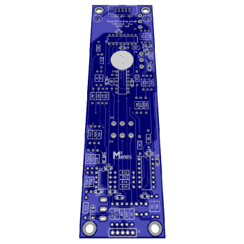
Bare PCB
The main PCB for building the M²Synth ADSR Envelope Generator 120 in either MOTM or MU format. All pots and switches are soldered direct to the back of the PCB (coloured blue on the PCB layout) so no panel wiring. You can also add the recommended jack socket breakout PCB 7215-722 which makes connecting to the sockets so much easier. Supplied complete with circuit schematic. PCB size 43.5 x 155mm.
For more info on this module, module specific build guide, general build info (Basics), PCB layout & parts list, see the M² Learn More section.
Power Supply Voltage
M2Synth modules are designed for +/-12V operation and we use a 10-pin IDC box header as our standard power supply connector. MOTM and MU systems use a different header and operate at +/-15V. To cater for the higher voltage and different power supply connectors we have an in-line voltage regulator conversion module if you intend to install the finished module in your own MOTM/MU system.
The regulator module can handle up to +/- 100mA maximum although we suggest +/-90mA is a practical safe limit. The module has the added advantage of providing a stable +/-12V to the module and reduces the risk of supply voltage fluctuations from other modules or power supply drift from affecting the supplied module. This ready assembled and tested module can be ordered along with the PCB.
Complete Kit
We can supply the ADSR 120 as a complete kit of parts for MOTM or MU formats offering a saving over purchasing items individually.
Ready Built
Prefer not to solder, a ready assembled version in MU or MOTM versions can be purchased direct from our dedicated website at m2synth.com
Advice
This kit is not suitable for those new to electronics assembly although it does not require test equipment to calibrate the module. For more info about assembling M²Synth modules see this guide

