Warning - Please read: This project involves the use of lethal mains potential voltages so do not attempt this build unless you have the necessary knowledge or have assistance from someone able to work safely with 110Vac / 230Vac. |
We have made the task of building a mains power supply easier through the use of a PCB mounted transformer but the risk of contact with mains voltages on the underneath of the PCB and around the Faston connectors remains. This power supply requires a mains rated fuse on the incoming power supply line. |
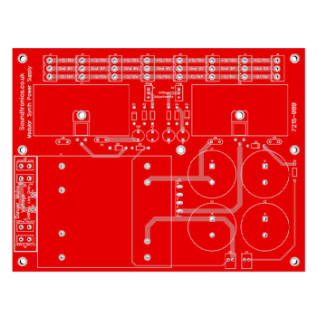
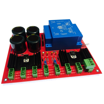
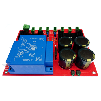
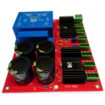
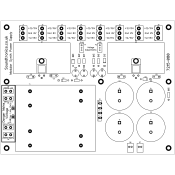
Introduction: This product is just for the bare PCB to build a linear bipolar power supply. Component kits and other accessories are available separately. The PCB is quite large at 183 x 140mm as it contains both the transformer and up to 8 power distribution sockets. Why a linear power supply which are larger, less efficient and more expensive than switch mode power supplies? A good quality switch mode supply should do the job nicely but many low cost switch mode supplies create switching frequency noise which can find its way into your audio circuits. After the last few years, we have come to the conclusion to keep the power supply out of the modular cabinet for two reasons - keeping the mains earth separate from the 0V and heat rise in the cabinet due to the power supply components. However, this power supply is versatile enough to allow you to adopt your own preference. At a push, it could be mounted behind a 1U by 5U high panel front, it could be mounted on the side wall or base of a modular cabinet with a degree of planning of the module layout. The third option which is the method we are adopting is to house the power supply in an external case and use it as a central point of power distribution to modular cabinets and synth cases.
Power Supply Design: A fairly standard design based on the datasheets for the LM317 & LM337 variable voltage regulators. How it differs is in its implementation for use with synths and DIY construction. The power supply can accept either a 0-12V, 0-12V or a 0-15V, 0-15V transformer depending on the output required. For 15-0-15V output then the 0-15V, 0-15V transformer is a must. For MFOS modules, 12-0-12V is the more common supply required and you can use either transformer. If your total load is less than 1A per rail then use the 0-12V, 0-12V transformer as it will keep heat losses to a minimum. Above 1A per rail then go for the 0-15V, 0-15V transformer.
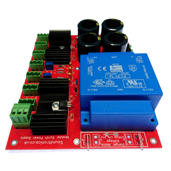
A bit about the transformers, they are made by a company called Block and are fully certified to various international standards. The transformer is fully encapsulated and has the following specification:
- Twin 115Va.c. 50 to 60Hz primary windings for series or parallel connection
- Isolating transformer for the safe electrical isolation of the input and output sides (SELV & PELV)
- Low profile compact design
- Maximum ambient temperature
- Vacuum epoxy resin moulded to UL94-V0 rating
- Self-extinguishing potting material
- Double section glass fibre reinforced polyamide bobbins
- 100% electrical and flash tested
- Low inter-winding capacitance
- Low radiated noise
- Standard: EN60742, VDE 0551, IEC 61558
The transformer is rated at 42W total or 21W / rail. This give a maximum output winding current of 1.6A / rail for the 0-12V, 0-12V transformer or 1.4A for the 0-15V, 0-15V transformer. In practice, the power supply output current will depend on the output voltage, the transformer voltage rating and the amount of capacitor smoothing, see performance figures below.
The mains power connection to the transformer is via Faston connectors and where they are soldered determines the input voltage of 115Vac or 230Vac. We recommend using the 10,000uF smoothing capacitors as a minimum but at currents over 1A, use even larger ones as long as their diameter does not exceed 30mm and their working voltage is 25Vdc minimum.
The output voltage stability is very good on the positive rail, the negative rail has slightly more droop at high currents but well within the the synth modules tolerance. Two on-board presets are used to set the output voltage and a pair of LEDs indicate the presence of a voltage on either rail. Do use the LEDs even is the power supply is fully enclosed as they draw the minimum operating current needed for the voltage regulators to function correctly.
Tips:
- You muse fuse the mains supply to the transformer primary winding, a 2A fuse should be fine
- The transformer will easily reach 60 deg C as will the regulator heatsinks. Ensure the enclosure is well ventilated and that its internal temperature never exceeds 40 Deg C. If you use in a hot environment, consider forced ventilation using a fan
- Mount the PCB horizontal if you are running it continuously at high currents to ensure adequate heat dissipation. Derate if mounted vertically and never mount upside down
- Adjust the output voltage before connecting to your synth modules and again after you have a base load
Performance:
There are 4 permutations for the power supply, namely whether the output voltage is +/-12V or +/-15V and whether you use a 0-12V 0-12V or a 0-15V 0-15V transformer. Each option has benefits and limitations. The 0-12V 0-12V transformer will run cooler than the 0-15V 0-15V transformer but with less current available. The tables below detail the performance for each option so you can make an informed decision. Most MFOS and YuSynth modules specify the load current so you can work out what the total load current should be plus add say 30% for luck.
Transformer | 0-12V, 0-12V | Ambient 23 Deg C | |
Load I (per rail) | O/P Voltage | Regulators Temperature Rise | Average Noise |
0.2A | +12V, -12V | +10C | +/-2mV |
0.5A | +11.99V, -11.96V | +14C | +/-2mV |
0.8A | +11.97V, -11.92V | +22C | +/-2mV |
1A | +11..96V, -11.88V | +23C | +/-2mV |
Output voltage reset to +/-12V | |||
1.2A | +11.96V, -11.96V | +25C | +/-3mV |
1.3A | +11.96V, -11.96V | +25C | +/-3mV |
1.4A | +11.96V, -11.66V | +26C | +3mV, -100mV |
Suggest maximum output at +/-12V is 1.2A per rail ( 28.8W) | |||
0.2A | +15V, -15V | +10C | +/-2mV |
0.4A | +14.99V, -14.99V | +12C | +/-2mV |
0.52A | +14.99V, -14.87V | +15C | +2mV, -75mV |
Suggest maximum output at +/-15V is 0.45A per rail ( 13.5W) | |||
Transformer | 0-15V, 0-15V | ||
0.2A | +12V, -12V | +12C | +/-2mV |
0.5A | +11.99V, -11.93V | +22C | +/-2mV |
0.8A | +11.99V, -11.98V | +30C | +/-2mV |
1A | +11.99V, -11.88V | +34C | +/-3mV |
Output voltage reset to +/-12V | |||
1.2A | +12V, -11.97V | +40C | +/-3mV |
1.4A | +12V, -11.96V | +43C | +/-3mV |
1.5A | +12V, -11.96V | +46C | +/-3mV |
1.6A | +11.99V, -11.93V | +50C | +/-3mV |
1.7A | +11.96V, -11.92V | +50C | +/-3mV |
1.8A | +11.96V, -11.92V | +50C | +/-3mV |
1.9A | +11.96V, -11.92V | +50C | +/-3mV |
2A | +11.96V, -11.52V | +48C | +3mV, -100mV |
Suggest maximum output at +/-12V is 1.5A per rail ( 36W) | |||
Forced cooling recommended | |||
0.2A | +15V, -15V | +7C | +/-2mV |
0.5A | +14.99V, -14.95V | +16C | +/-2mV |
0.8A | +14.99V, -14.91V | +26C | +/-2mV |
1A | +14.99V, -14.90V | +30C | +/-3mV |
Output voltage reset to +/-15V | |||
1.2A | +14.99V, -14.99V | +30C | +/-3mV |
1.3A | +14.99V, -15.61A | +30C | +3mV, -100mV |
Suggest maximum output at +/-15V is 1.2A per rail ( 36W) |
Parts List
Reference | Description | Part No. | Quantity |
Faston 6.35mm angle Connectors | 1251-041 | 2 | |
J1-J8 | Power distribution PCB Sockets | 1251-054 | 8 |
T1 | Block transformer FL 42/12 or FL42/15 depending on voltage | 1490-033 or 1490-044 | 1 |
U1 | LM317T | 2230-221 | 1 |
U2 | LM337T | 2230-231 | 1 |
U1, U2 | Heatsink 6.8 C/W, Aavid Thermalloy 1.25GY-50 | 2700-191 | 2 |
R2, R4 | 240R 0.25W 1% Metal Film Resistor | 7163-036 | 2 |
R5, R6 | 1k2 0.25W 1% Metal Film Resistor | 7163-053 | 2 |
R1, R3 | 1k8 0.25W 1% Metal Film Resistor | 7163-057 | 2 |
D2, D3, D4, D5 | 1N4002 | 7212-484 | 4 |
D1 | Bridge Rectifier GBU8G | 7212-487 | 1 |
C5, C6, C9, C11 | 100nF Ceramic Capacitor | 7212-749 | 4 |
P1, P2 | 1k Multiturn preset | 7212-854 | 2 |
C1, C2, C3, C4 | 10,000uF 35V Snap In Electrolytic Capacitor | 7213-125 | 4 |
C10, C12 | 1uF 25V Tantalum Capacitor | 7213-205 | 2 |
C7, C8 | 10uF 25V Tantalum Capacitor | 7213-208 | 2 |
D6, D7 | LED | 7213-910 | 2 |
In addition to the above parts, PCB stand-offs and mounting screws, Mains power connector / mains switch / mains fuse.
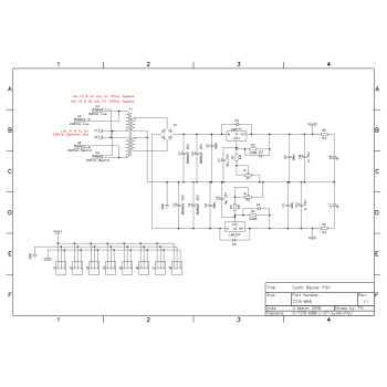
See the 'Downloads' tab for a XPS format copy of the schematic which can be viewed on Win 7 or later PCs.