YuSynth ADSR
Introduction
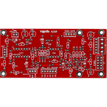
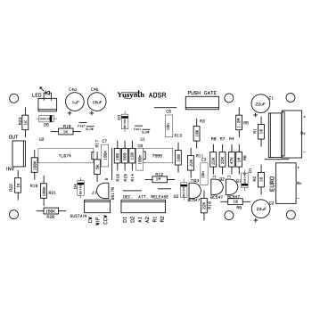
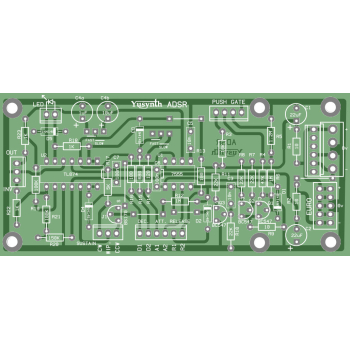
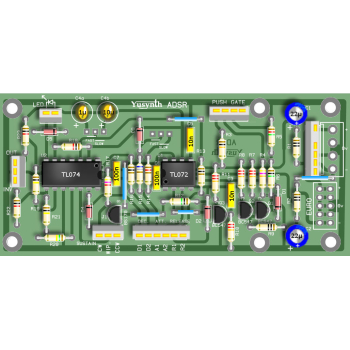
A bare double sided PCB 48x104mm (no need for the wire jumper links shown on the PCB layout) for the Yusynth ADSR synth module. These PCBs are manufactured by Soundtronics with a percentage of the sale going to the creator of the YuSynth - Yves Usson. These are early days for the YuSynth Modular Synth at Soundtronics, our plan is to stock PCBs for all of the projects as well as components, kits and front panels. This is going to take time but will eventually be as comprehensive as our MFOS range.
No components are included with the PCB but check out our Synth Components section where you should find what you need. We do suggest visiting the YuSynth ADSR project page for detailed information including Yves panel layouts but a summary is shown below.
Description
This new version of the ADSR module provides a control voltage that makes possible shaping the envelope of a continuous sound. It is mainly used to control the gain of a VCA module or drive the cut off frequency of a VCF module. As usual it is not restricted to these two obvious applications and can be extended to the control of many others modules.
- Attack duration : 1ms to 1s (short option) 5ms to 10s (long option)
- Decay duration : 1ms to 1s (short option) 5ms to 10s (long option)
- Sustain level : 0 to 10V
- Release duration : 1ms to 1s (short option) 5ms to 10s (long option)
The direct ADSR signal is available on one output within 0 to 10V range and the inverted ADSR signal is available on a second output either within 0 to -10V range or 10V to 0V range.
A push button is available to manually generate a direct GATE signal. The intensity of the output signal can be visualised by means of a simple LED.
The power draw of this module is rather low : 10mA +15V rail, 3.6 mA -15V rail.
The heart of this circuit is based on an original idea by Jonathan Jacky (1980, see references at the end of this page).
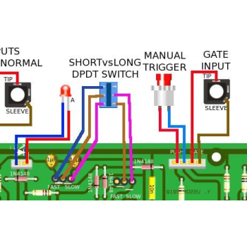
The PCB provides jumpers to select the short ADSR versus long ADSR option (a DPDT switch can be added to toggle between).
The PCB can accept a choice of three types of power connector, it can be either a Synthesizers.com 6 pins MTA connector, a MOTM 4 pins MTA96 connector or a 10-pin Eurorack connector.
The module was designed to work with a +15V/0V/-15V PSU but can be used without modifications with a +12V/0V/-12V PSU, however the output levels will be lower (around 8V instead of 10V)
Circuit
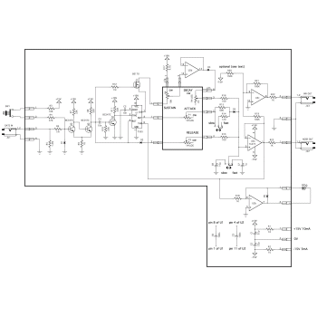
Click on the schematic thumbnail above for the circuit diagram.
The schematic of this module is rather simple and uses very common components. The 555 core of the schematic is based on an original idea by Jonathan Jacky that was published in Electronics ("Two-chip generator shapes synthesizer's sounds" Electronics #11, September 1980 : 137-138). This core has inspired other DIYers (Tom G.-EFM, René Schmitz).
Q1 and Q2 operate as a Schmitt trigger and turn any input signal as a suitable GATE signal. D1 protects the circuit from negative voltages. The trigger threshold is 2V. Diodes D2 to D4 are used to dispatch the charge and discharge current of the timing capacity C7/C8 (10µF/35V tantalum) through the potentiometers P1,P2 & P4. The 7555 chip (U1) is wired as a monostable timer. One OPA (TL074) is used to buffer the SUSTAIN voltage and avoids interference with the DECAY settings (otherwise the DECAY time would be affected by the SUSTAIN level). Two OPAs are used as a simple voltage follower and a voltage inverter, respectively. The fourth OPA drives the control LED. Note that J1 (BS170) has been introduced to break the DECAY circuit when the GATE signal returns to 0V before the DECAY cycle is finished. This insures that the capacitor will discharge through the RELEASE potentiometer rather through the DECAY circuit. Preferred behaviour of keyboardists...?
Wiring
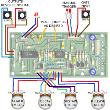
The wiring schematic image in the above thumbnails show the panel wiring to the pots and sockets etc.
Setting and Trimming
No setting up or trimming required
Parts List
The parts list below is direct from the YuSynth website.
The parts list excludes knobs although we have standardised on the Cliff KM20B but it does include 1/4" jack sockets. All parts are available individually (use the part number in the search box above) or as a components kit that excludes sockets and knobs.
Reference | Value | Part No. | Qty |
U1 | 7555 (or any other CMOS version of the NE555, DO NOT USE A NE555 !) | 7212-500 | 1 |
U2 | TL074 | 7212-544 | 1 |
J1 | BS170 | 7212-405 | 1 |
Q1, Q2, Q3 | BC547C or equivalent (mind the pinout !) | 7212-401 | 3 |
D1,D2,D3,D4, D5 | 1N4148 | 7212-480 | 4 |
R1,R2, R9 | 10 ohms | 7163-007 | 3 |
R13,R16 | 100 ohms | 7163-027 | 2 |
R14 | 120 ohms | 7163-029 | 1 |
R15 | 680 ohms | 7163-047 | 1 |
R18,R22,R23 | 1K | 7163-051 | 3 |
R17 | 4.7k | 7163-067 | 1 |
R3 | 10k | 7163-075 | 1 |
R7,R8,R10,R11 | 22k | 7163-083 | 4 |
R4 | 47k | 7163-091 | 1 |
R19, R21 | 100k | 7163-099 | 2 |
R20* | 150k* optional, sets the start level for inverted output (see text) | 7163-103 | 1 |
R6, R12 | 1M | 7163-122 | 1 |
R5 | 1.2M | 7163-128 | 1 |
P1,P2,P3 | 1M log | 7300-070 | 3 |
P4 | 10k lin | 7300-230 | 1 |
C3,C5 | 10n polyester film | 7212-713 | 2 |
C6,C7 | 100nF ceramic or polyester film | 7212-749 | 3 |
C4a | 1µF 35V tantalum | 7213-210 | 1 |
C4b | 10µF 35V tantalum | 7213-212 | 1 |
C1,C2 | 22µF 35V polarised | 7213-113 | 2 |
LD1 | Panel Mount | 7213-900 | 1 |
LD1 | LED, red low current | 7213-901 | 1 |
JK1,JK2,JK3 | female jack socket | 7212-203 | 3 |
SW1 | push button (push to make) | 7212-253 | 1 |
R17 : sets the range of the inverted output, if you use a 150K for R17 the inverted output will start from 10V (quiet state) to 0V (full range). If you don't install R17 (leave its place empty) then the range will be 0V (quiet state) to -10V (full range).