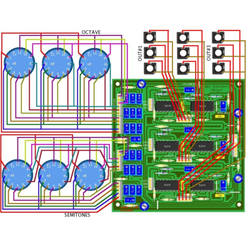
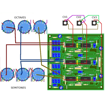
This utility modules provides switchable discrete CVs with useful intervals such as :
- octaves; eleven 1V steps from 0V to 10V (useful to control the yusynth VCOs which have no octave range switches);
- semitones; eleven 1/12 V steps from -0.4166V to 0.4166V (useful to detune a VCO with semitone intervals)]
OCTAVE | VALUE | SEMITONE | VALUE |
0 | 0 V | -5 | -0.4166 V |
1 | 1 V | -4 | -0.3333 V |
2 | 2 V | -3 | -0.2500 V |
3 | 3 V | -2 | -0.1666 V |
4 | 4 V | -1 | -0.0833 V |
5 | 5 V | 0 | 0 V |
6 | 6 V | +1 | 0.0833 V |
7 | 7 V | +2 | 0.1666 V |
8 | 8 V | +3 | 0.2500 V |
9 | 9 V | +4 | 0.3333 V |
10 | 10 V | +5 | 0.4166 V |
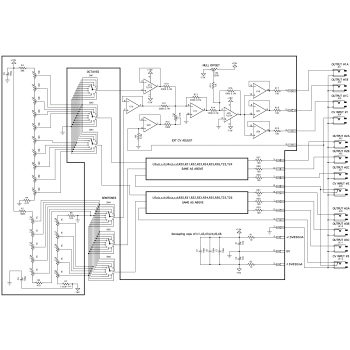
These stepped CVs are available independently on three voices and for each voice three buffered outputs are provided in order to drive more than one module (these are not multiples but true electrically separated and buffered outputs).
Also for each voice, an external CV can be summed to the stepped voltages. These inputs are intended for connecting external controllers such as a keyboard or a sequencer. Note that the input of voices 2 and 3 are defaulted to the previous input. For example if one connects a keyboard CV to IN #1 then this CV is echoed on the two others voices. But if one connects three different CVs on the three inputs, then each voice is only driven by the corrsponding input.
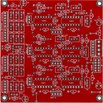
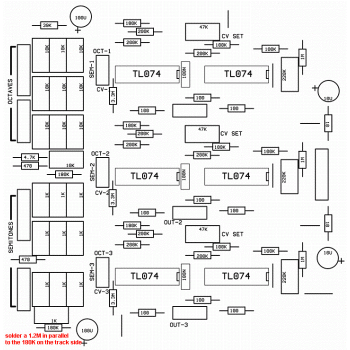
IMPORTANT NOTE : R7 must be 156K. Because there is no standard value for this resistor, we will have to use a trick. 156k can be obtain by connecting a 180K resistor and a 1.2M resistor in parallel. To do so, install the 180K resistor as shown on the component overlay and solder the 1.2M on the track side to the same pads as for the 180K resistor.
Parts List
The parts list below is direct from the YuSynth website. Customers have pointed out a number of discrepancies between the parts list, schematic and PCB on the YuSynth website. We have documented these differences on the kit of parts page here and strongly recommend referring to this revised list when assembling the PCB.
All parts are available individually (use the part number in the search box above) or as a components kit that excludes sockets and knobs.
Reference | Value | Part No. | Qty |
U1,U2,U3,U4,U5,U6 | TL074 | 7212-854 | 6 |
R1,R2 | 10 ohm | 7163-007 | 2 |
R17,R18,R19,R27,R28,R29,R37,R38,R39 | 100 ohm | 7163-027 | 9 |
R6,R8 | 470 ohm | 7163-047 | 2 |
R4 | 4.7k | 7163-067 | 1 |
R3 | 39k | 7163-089 | 1 |
R14,R16,R24,R26,R34,R36 | 100K 0.1% | 2000-161 | 6 |
R7 | 156K (a 180K in parallel with a 1.2M) | 7163-105 7163-128 | 1 |
R5,R12,R22,R32 | 180K | 7163-105 | 4 |
R10,R11,R13,R20,R21,R23,R30,R31,R33 | 200K 0.1% | 2000-174 | 9 |
R15,R25,R35 | 1M | 7163-122 | 3 |
R9,R19,R29 | 3.3M | 7163-123 | 3 |
C5,C6,C7 | 100nF | 7212-749 | 3 |
C1,C2 | 10µF or 22µF/35V electro. | 7213-113 | 2 |
C3,C4 | 100µF/35V electro. | 7213-115 | 2 |
T11,T12,T13,T14,T14,T15,T16,T17,18,T19,T20 | 1K 10 (or 15 or 25) turn trimmer | 7212-854 | 10 |
T1,T2,T3,T4,T5,T6,T7,T8,T9,T10 | 10K 10 (or 15 or 25) turn trimmer | 7212-857 | 10 |
T21,T23,T25 | 47K 10 (or 15 or 25) turn trimmer | 7212-859 | 3 |
T22,T24,T26 | 220K 10 (or 15 or 25) turn trimmer | 7212-861 | 3 |
Jk1,Jk2,Jk3,Jk4,Jk5,Jk6,Jk7,Jk8,Jk9,Jk10,Jk11,Jk12 | 6,5 mm jack socket | 7212-112 | 1 |
Trimming
It is important to use a high precision DVM at least 4000 pts.
- Set all the OCTAVE rotaries to the 0 position (counter clockwise position) and the SEMITONES rotaries to the 0 position (middle position)
Offset trimming :
- Connect the DVM to one of the outputs of channel/voice #1 (use 10mV/20mV DC range)
- Adjust T22 such that you measure 0mV +/- 0.2mV at the output.
- Connect the DVM to one of the outputs of channel/voice #2 (use 10mV/20mV DC range)
- Adjust T24 such that you measure 0mV +/- 0.2mV at the output.
- Connect the DVM to one of the outputs of channel/voice #3 (use 10mV/20mV DC range)
- Adjust T26 such that you measure 0mV +/- 0.2mV at the output.
Octave trimming :
- Connect the DVM to one of the outputs of channel/voice #1 (use 1V/2V DC range)
- Set the octave rotary (channel #1) to 1
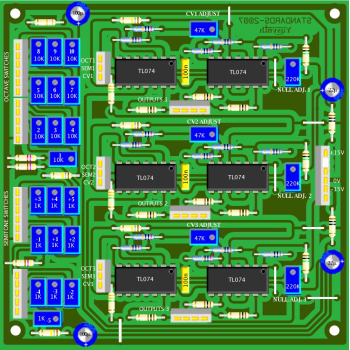
- Adjust T10 (noted 1 on the component layout diagram) such that you obtain 1V +/-0.001V at the output
- Set the octave rotary (channel #1) to 2
- Adjust T9 (noted 2 on the component layout diagram) such that you obtain 2V +/-0.001V at the output
- Set the range of the DVM to 10V/20V DC
- Set the octave rotary (channel #1) to 3
- Adjust T8 (noted 3 on the component layout diagram) such that you obtain 3V +/-0.001V at the output
- Set the octave rotary (channel #1) to 4
- Adjust T7 (noted 4 on the component layout diagram)such that you obtain 4V +/-0.001V at the output
- Set the octave rotary (channel #1) to 5
- Adjust T6 (noted 5 on the component layout diagram)such that you obtain 5V +/-0.001V at the output
- Set the octave rotary (channel #1) to 6
- Adjust T5 (noted 6 on the component layout diagram)such that you obtain 6V +/-0.001V at the output
- Set the octave rotary (channel #1) to 7
- Adjust T4 (noted 7 on the component layout diagram)such that you obtain 7V +/-0.001V at the output
- Set the octave rotary (channel #1) to 8
- Adjust T3 (noted 8 on the component layout diagram)such that you obtain 8V +/-0.001V at the output
- Set the octave rotary (channel #1) to 9
- Adjust T2 (noted 9 on the component layout diagram)such that you obtain 9V +/-0.001V at the output
- Set the octave rotary (channel #1) to 10
- Adjust T1 (noted 10 on the component layout diagram) such that you obtain 10V +/-0.001V at the output
Semitone trimming :
- Connect the DVM to one of the outputs of channel/voice #1 (use 1V/2V DC range)
- Set the octave rotary (channel #1) to 0
- Set the semitone rotary (channel #1) to -5
- Adjust T20 (noted -5 on the component layout diagram) such that you obtain -0.4166V +/-0.0001V at the output
- Set the semitone rotary (channel #1) to -4
- Adjust T19 (noted -4 on the component layout diagram) such that you obtain -0.3333V +/-0.0001V at the output
- Set the semitone rotary (channel #1) to -3
- Adjust T18 (noted -3 on the component layout diagram) such that you obtain -0.2500V +/-0.0001V at the output
- Set the semitone rotary (channel #1) to -2
- Adjust T17 (noted -2 on the component layout diagram) such that you obtain -0.1666V +/-0.0001V at the output
- Set the semitone rotary (channel #1) to -1
- Adjust T16 (noted -1 on the component layout diagram) such that you obtain -0.0833V +/-0.0001V at the output
- Set the semitone rotary (channel #1) to +1
- Adjust T15 (noted +1 on the component layout diagram) such that you obtain 0.0833V +/-0.0001V at the output
- Set the semitone rotary (channel #1) to +2
- Adjust T14 (noted +2 on the component layout diagram) such that you obtain 0.1666V +/-0.0001V at the output
- Set the semitone rotary (channel #1) to +3
- Adjust T13 (noted +3 on the component layout diagram) such that you obtain 0.2500V +/-0.0001V at the output
- Set the semitone rotary (channel #1) to +4
- Adjust T12 (noted +4 on the component layout diagram) such that you obtain 0.3333V +/-0.0001V at the output
- Set the semitone rotary (channel #1) to +5
- Adjust T11 (noted +5 on the component layout diagram) such that you obtain 0.4166V +/-0.0001V at the output
External CV trimming :
- Set all the OCTAVE rotaries to the 0 position (counter clockwise position) and the SEMITONES rotaries to the 0 position (middle position)
- Connect the DVM to one of the outputs of channel/voice #1 (use 10V DC range)
- Connect a calibrated voltage source set to 5.000V +/-0.001V to the IN #1 input
- Adjust T21 such that you obtain 5.000V +/-0.001V at the output
- Connect the DVM to one of the outputs of channel/voice #2 (use 10V DC range)
- Connect a calibrated voltage source set to 5.000V +/-0.001V to the IN #2 input
- Adjust T23 such that you obtain 5.000V +/-0.001V at the output
- Connect the DVM to one of the outputs of channel/voice #3 (use 10V DC range)
- Connect a calibrated voltage source set to 5.000V +/-0.001V to the IN #3 input
- Adjust T25 such that you obtain 5.000V +/-0.001V at the output