YuSynth Diode Ladder VCF
Introduction
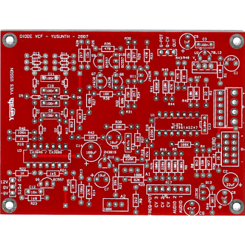
A bare double sided PCB (no need for the wire jumper links shown on the PCB layout) for the Yusynth Diode ladder synth module. These PCBs are manufactured by Soundtronics with a percentage of the sale going to the creator of the YuSynth - Yves Usson. These are early days for the YuSynth Modular Synth at Soundtronics, our plan is to stock PCBs for all of the projects as well as components, kits and front panels. This is going to take time but will eventually be as comprehensive as our MFOS range.
No components are included with the PCB but check out our Synth Components section where you should find what you need. We do suggest visiting the YuSynth Diode VCF project page for detailed information including Yves panel layouts but a summary is shown below.
Erratum
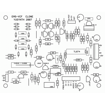
There are two C13's shown on the YuSynth PCB, the one by C15 is correct. The C13 next to the TL074 is 100nF.
C14 is shown incorrectly orientated on the YuSynth PCB layout, the +ve lead goes in the pad nearest R42. - Thanks to Arsenios for spotting this.
Silk screen for R47 shows it as 10k, should be 39k or higher - see YuSynth website for more info.
C4, 1uF 63V is shown as C6 on the PCB, should be C4
C6 47uF 35V, the + lead goes to the pad nearest the board edge.
Description
Well, here is another classical and very special filter based on the EMS diode ladder filter!
This filter has a sound of its own and is the signature of the classical Pink Floyd's song "On the run".
Yves Usson's aim here was to design a quite faithful copy of this mythic filter while using components that minimize the burden of selecting a great number of matched transistors. This is why he used transistor arrays (CA3046, CA3096). However, because the CA3096 has become a rare part and is now overpriced, he also designed a PCB with discrete trannies to replace it which is this version. As for all the other filters of his YUSYNTH project, he added an input and an output buffer to adapt this filter to the input and output levels of his modular system.
Yves also added an input for voltage control of the resonance : everything was there in the original module but was not made available, probably because of the limited size of the patch pin matrix of the AKS/VCS3...
Because, the YuSynth power supply standard is +15/-15V, also included is a power regulator IC (78L12) to convert +15V to +12V and a single transitor voltage regulator -15V to -9V (he wanted to use a 79L09 but changed my mind when he realized that this voltage regulator is quite a rare part and is difficult to source althouth we do stock them at Soundtronics!).
The PCB can accept a choice of three types of power connector, it can be either a Synthesizers.com 6 pins MTA connector, a MOTM 4 pins MTA96 connector or a 10-pin Eurorack connector.
The module is designed to work with a +15V/0V/-15V PSU
Circuit
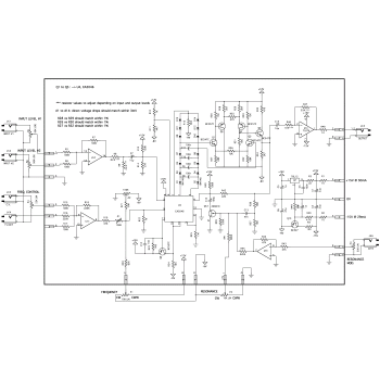
Click on the schematic thumbnail above for the circuit diagram.
Basically the circuit is built around the original core of the EMS filter, though Yves had to change some resistor values to compensate for the fact that the active components (NPN,PNP and JFET) are modern counterparts and some of their characteristics are different from the original parts.
The major additions are : a quadruple OPA that is used to buffer the various inputs (audio, CVs) and the output. The values of the resistors of these buffers may be adjusted to audio and CV levels of any modular system. Next, he introduced a voltage control input of the RESONANCE. Finally, a 78L12 and a PNP transistor to convert the power supply levels from +15V/-15V to +12V/-9V .
NOTE : the value of R47 can be changed to adjust the output level as see fit.
Wiring
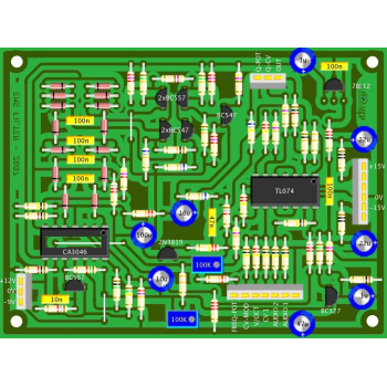
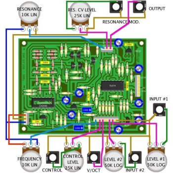
The wiring schematic image in the above thumbnails show the panel wiring to the pots and sockets etc.
Setting and Trimming
Adjusting trimmer A1 (V/OCT tracking)
IMPORTANT NOTE : don't expect a real V/octave tracking, one may reach a good V/octave tracking only over a maximum of 2 or 3 octaves (at best) !
- Set the RESONANCE pot to maximum in order to obtain auto-oscillation
- Connect a CV/GATE controller to the V/OCT input, set it to 0V
- Set the FREQUENCY pot such that you obtain a C3
- Set the CV/GATE controller to 2V
- Adjust A1 such that you obtain a C5
Adjusting trimmer A2 (init frequency)
- Set the RESONANCE pot to min value
- Set the FREQUENCY pot to min value
- Connect a 25Hz SQUARE signal to the INPUT
- Adjust the A2 in order to mute the OUTPUT
IMPORTANT NOTE : the "pinch voltage" of JFETs may vary significantly even when they come from the same batch, therefore if you experience some problems with the resonance potentiometer for example if you notice that the resonance range is rather limited and the filter cannot oscillate, change the value of R41 to 220K.
Parts List
The parts list below is direct from the YuSynth website.
The parts list excludes knobs although we have standardised on the Cliff KM20B but it does include 1/4" jack sockets. All parts are available individually (use the part number in the search box above) or as a components kit that excludes sockets and knobs.
Reference | Value | Part No. | Qty |
U1 | TL074 | 7212-544 | 2 |
U2 | 78L12 (TO92 package) or 7812 (TO220 package) | 2230-031 | 1 |
U3 | CA3046 intersil transistor array (Q1 to Q5) CA3146 and CA3086 are possible substitutes | 7212-505 | 1 |
Q7,Q8,Q11 | BC547 | 7212-401 | 3 |
Q6,Q9,Q10 | BC557 | 7212-403 | 3 |
Q12 | 2N3819 JFET | 7212-404 | 1 |
Q13 | BC327 | 7212-413 | 1 |
D1,D2,D3,D4,D5,D6,D7,D8,D9, D10,D11,D12,D13,D14 |
1N4148, matched set of 14 for their direct voltage drop with a maximum tolerance of 3mV | 7212-483 | 1 |
R1,R2 | 10 ohms | 7163-007 | 2 |
R3 | 22 ohms | 7163-013 | 1 |
R4 | 150 ohms | 7163-031 | 1 |
R33,R35 | 470 ohms | 7163-043 | 2 |
R10,R22,R48 | 1K | 7163-051 | 3 |
R24 | 1.5K | 7163-055 | 1 |
R23,R37 | 1.8K | 7163-057 | 2 |
R9 | 2.2K | 7163-059 | 1 |
R28*,R29*,R34 | 2.7K *matched to 1% | 7163-061 | 3 |
R11,R50 | 4.7K | 7163-067 | 2 |
R8,R12 | 8.2K | 7163-073 | 2 |
R36,R46,R49 | 10K | 7163-075 | 3 |
R26*,R30*,R31 | 15K *matched to 1% | 7163-079 | 3 |
R42 | 22K | 7163-083 | 1 |
R14 | 27K | 7163-085 | 1 |
R21,R47** | 39K **may be changed to other values see notes | 7163-089 | 2 |
R19,R43,R44 | 47K | 7163-091 | 3 |
R27*,R32*,R38 | 68K *matched to 1% | 7163-095 | 3 |
R20 | 82K | 7163-097 | 1 |
R5,R6,R7,R15,R17,R40 | 100K | 7163-099 | 6 |
R13 | 150K | 7163-103 | 1 |
R16,R18,R39,R45 | 220K | 7163-107 | 4 |
R41 | 680K | 7163-118 | 1 |
R25 | 1M | 7163-122 | 1 |
C12 | 10nF polyester film | 7212-713 | 1 |
C13 | 47nF polyester film | 7212-717 | 1 |
C3, C13(Next to the TL084) | 100nF | 7212-749 | 1 |
C8*,C9*,C10*,C11* | 100nF *matched set to 1% (not mandatory) | 7212-793 | 1 |
C4,C5 | 1µF/50V | 7213-116 | 2 |
C7 | 10µF/50V | 7213-119 | 1 |
C1,C2,C15 | 22µF/50V | 7213-120 | 2 |
C6 | 47µF/50V | 7213-121 | 1 |
C14 | 100µF/25V | 7213-110 | 1 |
A1,A2 | 100K 10/15 turn trimmer | 7212-860 | 2 |
P1,P2 | 10K lin | 7300-230 | 2 |
P3,P4 | 25K lin | 7300-240 | 2 |
P5,P6 | 50K log | 7300-025 | 2 |
Jk1,Jk2,Jk3,Jk4,Jk5,Jk6 | female jack socket | 7212-206 | 1 |