YuSynth Dual Ring Modulator
Introduction
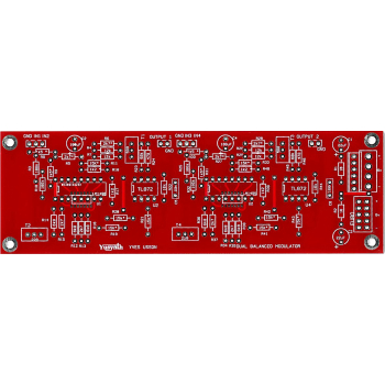
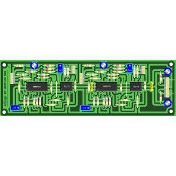
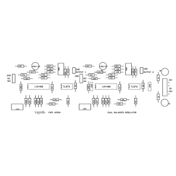
A bare double sided PCB (no need for the wire jumper links shown on the PCB layout) for the Yusynth Dual Ring Modulator synth module. These PCBs are manufactured by Soundtronics with a percentage of the sale going to the creator of the YuSynth - Yves Usson. These are early days for the YuSynth Modular Synth at Soundtronics, our plan is to stock PCBs for all of the projects as well as components, kits and front panels. This is going to take time but will eventually be as comprehensive as our MFOS range.
No components are included with the PCB but check out our Synth Components section where you should find what you need. We do suggest visiting the YuSynth Dual Balanced Modulator project page for detailed information including Yves panel layouts but a summary is shown below.
Erratum
Sorry but there are some small errors on the PCB. These are the ground connections to the input sockets are not connected to 0V and R16 is also not connected to 0V. R16 is simply corrected by solder bridging to R13. The input sockets can also be solder bridged to the perimeter 0V rail if you first scratch back the solder resist. Alternatively connect to the nearest 0V using insulated wire. The photo belows shows the solder bridge links, do these after installing the components.
Description
The balanced modulator or four quadrant multiplier, is a great classical module. it provides the same functions as those of a ring modulator. Its main purpose is to generate sounds with a complex overtone content such as bell sounds and other klang tones !
The principle of this circuit is based on a Gilbert cell contained in the classical LM1496 IC.
Basically, if one feeds the A input with a sinewave with frequency f1, that is sin(2πf1), and the B input with a sinewave with frequenc f2, that is sin(2πf2), one gets at the output the product these two signals, that is sin(2πf1) x sin(2πf2).
Due to trigonomic properties it reads :
in other words the output is a mixture of two sinewaves, one with frequency f1+f2 and the other with frequency f1-f2.
The PCB can accept a choice of three types of power connector, it can be either a Synthesizers.com 6 pins MTA connector, a MOTM 4 pins MTA96 connector or a 10-pin Eurorack connector.
Circuit
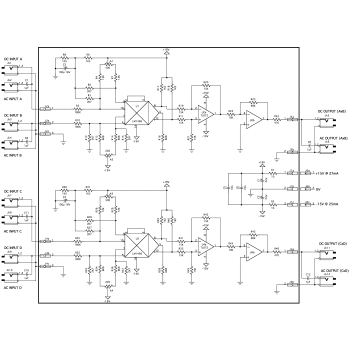
Click on the schematic thumbnail above for the circuit diagram.
The schematic of this balanced modulator is directly inspired by that of the Elektor's Formant (which is a mere adaptation of the application schematic of the LM1496 datasheet, see at the end of this page). Yves only changed the values of the input resistors in order to make the input signal levels compatible with the Moog/Dotcom standards (10V peak to peak) He also added an output stage that amplifies the output signal by 6.8 in order to obtain 10Vpp.
Wiring
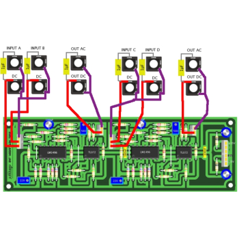
The wiring schematic image in the above thumbnails show the panel wiring to the pots and sockets etc.
Setting and Trimming
There are four trimmers to adjust : A1 to A4. These trimmers are used for cancelling the input signals. The settings are quite simple, you will need a signal generator that delivers a sinewave signal with a 10V (peak to peak) output amplitude. Here is how to proceed :
- Tune the generator on 1000Hz and set the output level of the generator to 10Vpp.
- Connect the output AxB (or CxD) of the module to an audio amplifier. Be sure to set the input potentiometer of the amplifier to a low value : the output level of the module is 10Vpp and most of the audio amplifiers expect an input level that doesn't exceed 1Vpp.
- Connect the signal generator to the input A (or C) with a capacitor (AC-INPUT). There, you must hear the 1000Hz signal at the output AxB (or CxD).
- Adjust the trimmer A2 (or A4) such that the 1000Hz signal can no longer be heard at the output.
- Disconnect the signal generator from input A (or C) and then connect the signal generator to the input B (or D) with a capacitor (AC-INPUT). There, you must hear the 1000Hz signal at the output AxB (or CxD).
- Adjust the trimmer A1 (or A3) such that the 1000Hz signal can no longer be heard at the output.
Now the module is ready to operate. A last check can be done by connecting the 1000Hz signal to both inputs A and B (AC inputs) : there you must hear a single signal of frequency twice as high (2000Hz).
Parts List
The parts list below is direct from the YuSynth website.
The parts list excludes knobs although we have standardised on the Cliff KM20B but it does include 1/4" jack sockets. All parts are available individually (use the part number in the search box above) or as a components kit that excludes sockets and knobs.
Reference | Value | Part No. | Qty |
U1,U3 | LM1496 or MC1496 | 7212-502 | 2 |
U2,U4 | TL072 | 7212-542 | 2 |
C5,C6 | 100nF polyester film | 7212-718 | 2 |
C1,C2 | 22µF/25V polarised | 7213-108 | 2 |
C3,C4 | 100µF/25V polarised | 7213-110 | 2 |
C7,C8,C9,C10,C11,C12 | 1µF polyester film unpolarised | 7212-724 | 6 |
R1,R2 | 10 ohms | 7163-007 | 2 |
R24,R46 | 470 ohms | 7163-047 | 2 |
R17,R18,R39,R40 | 1k2* 1% | 7163-053 | 4 |
R8,R9,R30,R31 | 1k5* 1% | 7163-055 | 4 |
R5,R6,R13,R15,R27,R28,R35,R37 | 2k7* 1% | 7163-061 | 8 |
R12,R14,R16,R34,R36,R38 | 6k8 | 7163-071 | 6 |
R22,R44 | 10k | 7163-075 | 2 |
R4,R7,R26,R29 | 12k 1% | 7163-077 | 4 |
R11,R19,R20,R21,R33,R41,R42,R43 | 15k 1% | 7163-079 | 8 |
R23,R45 | 68k | 7163-095 | 2 |
R3,R10,R25,R32 | 180k | 7163-105 | 4 |
A1,A3 | 500 ohms 10 tours vertical | 7212-853 | 2 |
A2,A4 | 220 ohms 10 tours vertical | 7212-852 | 2 |
Jk1 à Jk12 | socle jack 6,35mm | 7212-200 | 12 |