Introduction
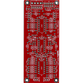
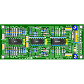
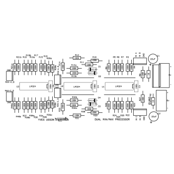
A bare double sided through hole plated PCB (no need for the wire jumper links shown on the PCB layout) 114x48mm for the Yusynth Steiner VCO synth module using the LM394. These PCBs are manufactured by Soundtronics with a percentage of the sale going to the creator of the YuSynth - Yves Usson. These are early days for the YuSynth Modular Synth at Soundtronics, our plan is to stock PCBs for all of the projects as well as components, kits and front panels. This is going to take time but will eventually be as comprehensive as our MFOS range.
No components are included with the PCB but check out our Synth Components section where you should find what you need. We do suggest visiting the YuSynth MinMax project page for detailed information including Yves panel layouts but a summary is shown below.
Erratum
Sorry but there is small error on the PCB.If you are using the Euro connector to power up the board then you will need to add the wire link as shown on the photo below. We also suggest bridging the two -ve 12V pins on the Euro with a solder bridge.
Description
The purpose of this module is to process multiple sources in order to retain two signals which are respectively the minimum and the maximum of the input signals. Basically, each submodule has two inputs that can be fed with either CVs or audio signals, and two outputs, one is the maximum value and the second is the minimum value. The two submodules can be chained to achieved more complex functions or combine more than two inputs.
The design of such a min-max processor can be addressed by two different approaches : current processing (see reference at the end of the page) or voltage processing. Yves preference was using the voltage one. This way the min-max processor can be built with elementary blocks such as adders, subtractors and full-wave rectifiers which only involve ordinary components (OPAs, resistors and diodes).
The min function or MIN(a,b) reads :
The absolute value operator is obtained using a full wave rectifier !
Besides, as a default the inputs are grounded, therefore if one plugs a signal in an input and nothing in the other, the signals collected at the MIN and MAX outputs are the negative and positive halves of the signal, respectively.
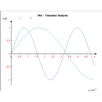
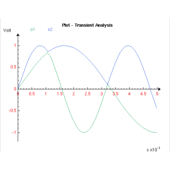
Thumbnail images above show the result of a spice simulation of the circuit based on Yves' schematic.
Circuit
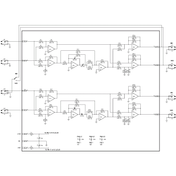
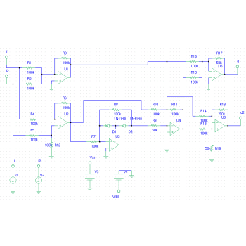
Click on the schematic thumbnail above for the circuit diagram but note the component values are for the 15V version only, see the BOM below for the 12V values..
Wiring
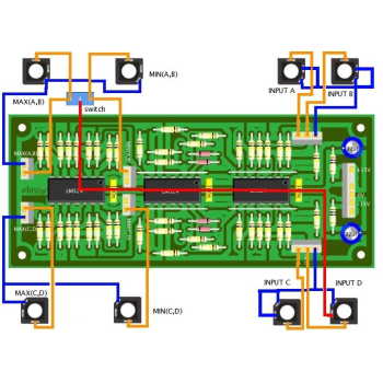
The wiring schematic image in the above thumbnails show the panel wiring to the pots and sockets etc.
Parts List
The parts list below is direct from the YuSynth website.
The parts list excludes knobs although we have standardised on the Cliff KM20B but it does include 1/4" jack sockets. All parts are available individually (use the part number in the search box above) or as a components kit that excludes sockets and knobs.
Reference | Value | Part No. | Qty |
U1,U2,U3 | LM324 or TL074 | 7212-571 | 3 |
D1,D2,D3,D4 | 1N4148 | 7212-480 | 4 |
R1,R2 | 10 | 7163-007 | 2 |
R3,R4,R5,R6,R7,R8,R9,R10,R11,R12,R13a,R13b,R14,R15,R16,R17,R18, R19a,R19b,R20a, R20b,R21a, R21b, R22,R23,R24,R25,R26,R27,R28,R29,R30,R31,R32a,R32b,R33,R34,R35,R36, R37,R38a,R38b,R39a,R39b,R40a,R40b |
100K 1% | 7163-099 | 46 |
JK1 to JK8 | jack socket | 7212-208 | 1 |
C3,C4,C5 | 100n | 7212-749 | 3 |
C1,C2 | 22µF 50V | 7213-113 | 2 |
SW1 | SPDT switch | 7212-250 | 1 |