YuSynth Saw-Animator
Introduction
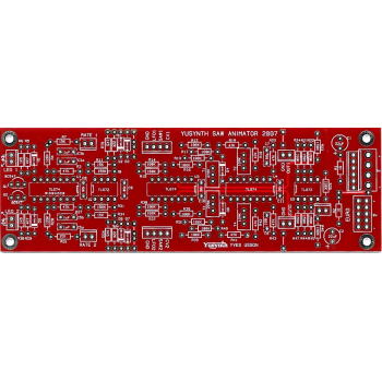
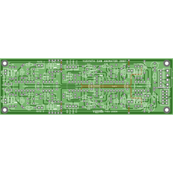
A bare double sided PCB (no need for the wire jumper links shown on the PCB layout) for the Yusynth Saw Animator synth module. These PCBs are manufactured by Soundtronics with a percentage of the sale going to the creator of the YuSynth - Yves Usson. These are early days for the YuSynth Modular Synth at Soundtronics, our plan is to stock PCBs for all of the projects as well as components, kits and front panels. This is going to take time but will eventually be as comprehensive as our MFOS range.
No components are included with the PCB but check out our Synth Components section where you should find what you need. We do suggest visiting the YuSynth Saw Animator project page for detailed information including Yves panel layouts but a summary is shown below.
Erratum
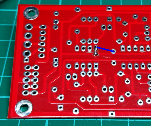
Sorry but there is small error on the PCB.Currently, pin 7 of U5 is connected to the positive track, this is incorrect, pin 8 should be connected to the positive track.
Cut the track close to pin 7 pad of U5, just as it joins the positive track. After soldering in the IC socket for U5, solder a link between pin 8 of U5 and the positive track. This can be achieved either with a link to C11 (solder in C11 first) or but scraping the solder resist on the positive track close to pin 8 of U5. The photo below shows the second option but a blue link signifies the first method.
Description
The Saw Animator module is a very interesting module when you whish to get that FAT sound, usually obtained with two or more sawtooth VCOs, but you are short of VCOs. You can get this typical sound with only one sawtooth VCO, thanks to Bernie Hutchins (JAES, 1981). The Digisound 80 has this wonderful module and Scott Bernardi designed a version of its own. The present module is a somehow simplified but yet efficient version. To get the best of this module, it must be used in conjunction with a mixer. Yves chose not to integrate a mixer within the module in order to benefit from the dry outputs which are very useful when used with a LFO instead of a VCO. When used with a sawtooth LFO and inputing fixed CVs in the MOD inputs, one can achieve some interesting phase shifted modulators such as quadrature modulation. Well the possibilities are numerous and it's up to your imagination...
The PCB can accept a choice of three types of power connector, it can be either a Synthesizers.com 6 pins MTA connector, a MOTM 4 pins MTA96 connector or a 10-pin Eurorack connector.
Circuit
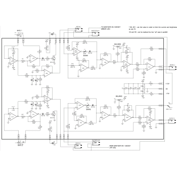
Click on the schematic thumbnail above for the circuit diagram. IMPORTANT NOTE : the circuit has been designed to work with balanced sawtooth signals ranging from -5V to 5V, if you intend to use it with unbalanced sawtooth or different peak to peak voltage you will have to recalculate some resistor values...
Wiring
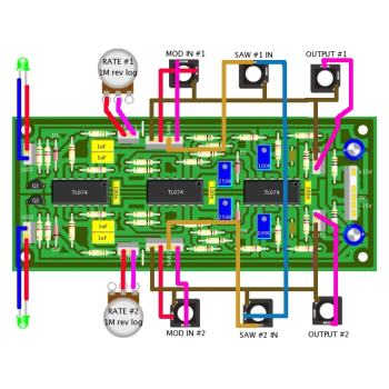
The wiring schematic image in the above thumbnails show the panel wiring to the pots and sockets etc.
Setting and Trimming
There are four trimmers to be adjusted. Note that the adjustment procedure is the same for T1 and T3 and for T2 and T4.
Setting of T1 (SHAPE trimmer).
- ground the MOD IN #1 input
- feed a balanced sawtooth (ranging -5V to 5V) to the SAW IN #1 input
- connect an oscilloscope to the OUTPUT #1 output
- check the shape of the output signal, it should look like one or another of the following waveshapes


5. adjust T1 in order to obtain a normal sawtooth waveshape 
Setting of T2 (BALANCE trimmer)
- adjust T2 in order that the output signal is balanced and ranges from -5V to +5V
Unground the MOD IN #1, you must see the sawtooth swaying at the rhythm of the internal LFO
Repeat the same settings to adjust T3 and T4.
Parts List
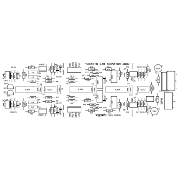
The parts list below is direct from the YuSynth website. The value in the parts list is the default value and may differ to that quoted in the schematic / PCB silk image.
The parts list excludes knobs although we have standardised on the Cliff KM20B but it does include 1/4" jack sockets. All parts are available individually (use the part number in the search box above) or as a components kit that excludes sockets and knobs.
| Reference | Value | Part No. | Qty |
| U2,U5 | TL072 | 7212-542 | 2 |
| U1,U3,U4 | TL074 | 7212-544 | 3 |
| Q1,Q2 | BC547C | 7212-401 | 2 |
| D1,D2,D3,D4,D5,D6,D7,D8 | 1N4148 | 7212-480 | 8 |
| R1,R2 | 10 ohm 5% | 7163-007 | 2 |
| R6,R10,R30,R33 | 1.5k 5% | 7163-055 | 4 |
| R5,R29 | 4.7k 5% | 7163-067 | 2 |
| R7,R11,R31,R34 | 15k 5% | 7163-079 | 4 |
| R9,R32 | 22k 5% | 7163-083 | 2 |
| R3*,R18,R19,R20,R27*,R41,R42,R43 | 47k 1%, *5% | 7163-091 | 8 |
| R12,R13,R14,R15,R16,R17,R35,R36,R37,R38,R39,R40 | 100k 1% | 7163-099 | 12 |
| R4,R28 | 120k 5% | 7163-101 | 2 |
| R8*,R21,R22,R23,R24,R26,R31*,R44,R45,R46,R47 | 150K 1%, * 5% | 7163-103 | 11 |
| C6,C7 | 100pF | 7212-734 | 2 |
| C8,C9,C10,C11 | 100nF | 7212-749 | 3 |
| C3(a,b),C4(a,b) | 2.2µF Wima 63V (or 2x1µF polyester film) | 7212-707 | 2 |
| C1,C2 | 22µF/25V electro. | 7213-108 | 2 |
| T2,T4 | 100K multi-turn trimmer | 7212-860 | 2 |
| T1,T3 | 250K or 220K multi-turn trimmer | 7212-861 | 2 |
| LD1,LD2 | Panel Mount | 7213-900 | 2 |
| LD1,LD2 | yellow LED | 7213-903 | 2 |
| P1,P2 | 1MC rev log potentiometer | 7300-180 | 2 |
| Jk1,Jk2,Jk3,Jk4,Jk5,Jk6 | 6,5 mm jack socket | 7212-206 | 6 |

