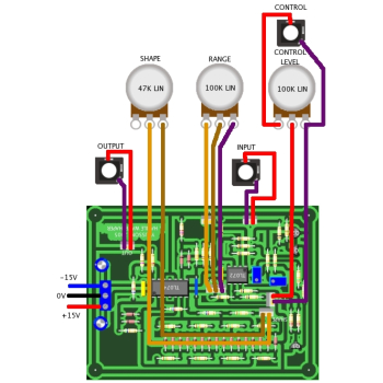
YuSynth Wavefolder
Introduction
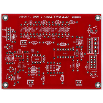
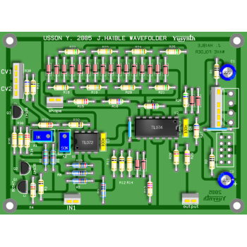
A bare double sided PCB 100x75mm (no need for the wire jumper links shown on the PCB layout) for the Yusynth Wavefolder synth module. These PCBs are manufactured by Soundtronics with a percentage of the sale going to the creator of the YuSynth - Yves Usson. These are early days for the YuSynth Modular Synth at Soundtronics, our plan is to stock PCBs for all of the projects as well as components, kits and front panels. This is going to take time but will eventually be as comprehensive as our MFOS range.
No components are included with the PCB but check out our Synth Components section where you should find what you need. We do suggest visiting the YuSynth Wavefolder project page for detailed information on this PCB.
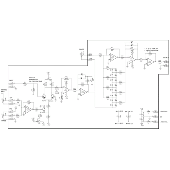
This module is based on Jürgen Haible's wavefolder B that Yves associated to a VCA at the input to dynamically control wavefolding, and with an amplifier to adjust the output level.
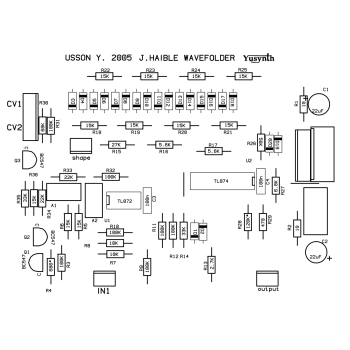
This circuit is made of three parts : the first one is based on U2, Q1 and Q3 and is a voltage controlled amplifier (VCA) and accepts an input signal ranging from -10V et +10V with a control voltage (CV1) ranging from 0 to 15V. The second part made of U1b, U1c and U1d and diodes D1 à D20 is actually Jürgen Haible's wavefolder. Next, the third part is a level amplifier which gain is set to obtain an output signal in the range -10V to 10V. By the way, if you need to modify the voltage range of the input and output signals, it is just a matter of changing the values of R20 & R21 for the input signal and that of R17 & R18 to adjust the output level.
Parts List
The parts list below is direct from the YuSynth website. The value in the parts list is the default value and may differ to that quoted in the schematic / PCB silk image.
The parts list excludes knobs although we have standardised on the Cliff KM20B but it does include 1/4" jack sockets. All parts are available individually (use the part number in the search box above) or as a components kit that excludes sockets and knobs.
| R4* Depends on input level | 7163-039 | 330R 0.25W 1% Metal Film Resistor | 1 |
| R29 | 7163-043 | 470R 0.25W 1% Metal Film Resistor | 1 |
| R4* Depends on input level | 7163-047 | 680R 0.25W 1% Metal Film Resistor | 1 |
| R13 | 7163-061 | 2k7 0.25W 1% Metal Film Resistor | 1 |
| R16,R17 | 7163-069 | 5k6 0.25W 1% Metal Film Resistor | 2 |
| R27 | 7163-071 | 6k8 0.25W 1% Metal Film Resistor | 1 |
| R7,R8 | 7163-075 | 10k 0.25W 1% Metal Film Resistor | 2 |
| R5, R6, R18, R19, R20, R21, R22, R23,R24, R25, R36 | 7163-079 | 15k 0.25W 1% Metal Film Resistor | 11 |
| R33,R34 | 7163-083 | 22k 0.25W 1% Metal Film Resistor | 2 |
| R15 | 7163-085 | 27k 0.25W 1% Metal Film Resistor | 1 |
| R14,R35 | 7163-087 | 33k 0.25W 1% Metal Film Resistor | 2 |
| R26,R28 | 7163-093 | 56k 0.25W 1% Metal Film Resistor | 2 |
| R30 | 7163-095 | 68k 0.25W 1% Metal Film Resistor | 1 |
| R3, R9, R10, R11, R12, R31, R32 | 7163-099 | 100k 0.25W 1% Metal Film Resistor | 7 |
| U2 | 7212-331 | Turned Pin 0.3 inch Dil IC Socket 8 Pin | 1 |
| U1 | 7212-332 | Turned Pin 0.3 inch Dil IC Socket 14 Pin | 1 |
| Q3 | 7212-401 | BC547C Diotec Bipolar NPN Transistor TO-92 | 1 |
| D1 to D20 | 7212-481 | 1N4148 3mV Matched Pairs | 10 |
| Q1, Q2 | 7212-492 | BC547C Hfe Matched Pair | 1 |
| U2 | 7212-542 | Dual Op-Amp BiFET TL072CP | 1 |
| U1 | 7212-544 | Quad Op-Amp BiFET TL074 | 1 |
| C3,C4 | 7212-749 | 100nF 5mm X7R Dielectric Radial Ceramic Capacitor | 2 |
| A1 | 7212-854 | Multiturn Cermet Preset Top Adjust SIL 1k | 1 |
| A2 | 7212-859 | Multiturn Cermet Preset Top Adjust SIL 50k | 1 |
| C1,C2 | 7213-113 | Radial Electrolytic Capacitor 22uF 35V | 2 |
| P2 | 7300-250 | Synth Pot 16mm 50k Lin | 1 |
| P1,P3 | 7300-255 | Synth Pot 16mm 100k Lin | 2 |
Setting and Trimming
- Set A1& A2 to mid-range.
- Connect the sinewave generator (freq. 1KHz, 10Vpp) to input 1, P1 turned fully clockwise (maximum signal).
- Connect the sinewave generator to the first input of your scope.
- Connect CV1 to 0V and turn P3 fully clockwise (maximum gain).
- Connect the output of the VCA (pin 1 of U2a) to the second input of the scope.
- Adjust the trimmer A1 in order to have a perfectly symmetrical sine wave at the output (the best way is to superimpose the trace of the sinewave at input and the one at the output). You may have also to play slightly with A2 as well to reduce gain if you have saturation on both the positive and negative crests of the output sinewave.
- Next, turn P1 fully counter-clockwise (no CV). Adjust A2 in order to completly mute the output signal.

